CNC Machining Design Guide

Introduction
In this complete guide to designing for CNC machining, we’ve compiled basic & advanced design practices and tips to help you achieve the best results for your custom parts. Whether you’re prototyping or ready for large-scale production, following these guidelines will ensure your designs are optimized for efficiency, cost, and performance.
CNC Machining Basics
CNC machining has become one of the most popular methods for prototyping and manufacturing today, especially for metal parts.
While most of the technical details—like tool selection, spindle speed, and cutting depth—are handled by the machine shop, there’s still plenty you can do during the design phase to ensure your part is not only manufacturable but also cost-efficient.

When designing a part for CNC machining, it’s important to think about the manufacturing effort. How much work goes into sourcing the material, setting up the tooling, preparing the part, and machining it to its final shape? By making smart design choices, you can significantly reduce the effort involved, which means lower costs and faster turnaround times. Want to dive deeper into optimizing the manufacturing process? Our DFM experts are here to help.
Before diving into advanced practices, it’s important to understand how CNC machines work.
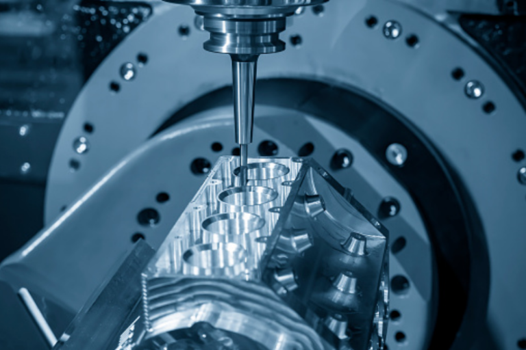
CNC machining is a subtractive manufacturing process where material is precisely removed from a solid block using high-speed cutting tools—spinning at thousands of RPM—to create parts directly from a CAD model. This method works for both metals and plastics.
CNC-machined parts offer excellent dimensional accuracy and tight tolerances, making it ideal for both large-scale production and one-off custom jobs. In fact, when it comes to metal prototypes, CNC machining remains the most cost-effective option, even compared to 3D printing.
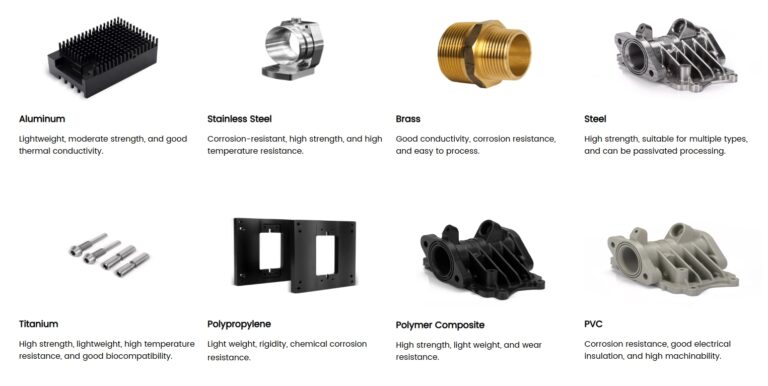
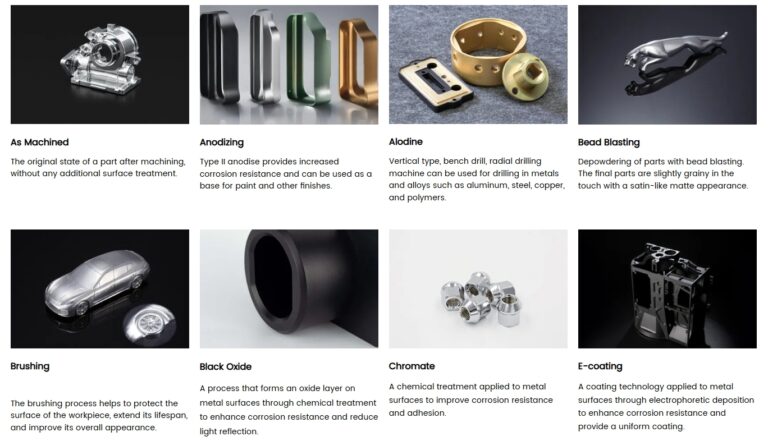
Read our CNC machining(Details of Material Selection & Surface treatment).


Advantages and Disadvantages of CNC Machining
Advantages of CNC Machining
- Highly Automated: CNC machining is highly automated, making it cost-competitive for both high-quality one-off parts and mid-to-high volume production.
- Material Versatility: CNC can machine almost any material, giving you flexibility in material selection.
- High Accuracy: CNC produces parts with exceptional dimensional accuracy, ensuring consistent quality.
- Superior Physical Properties: CNC parts often have better physical properties and experience less internal stress compared to parts produced by other methods.
- Low Setup Costs: Initial setup costs are relatively low, and jobs can be easily repeated for future production runs.
- Fast Iterations: Design changes or adjustments can be quickly implemented during development or even mid-production.
- Customization Options: CNC allows for easy variations and customizations, making it perfect for tailored part designs.
Disadvantages of CNC Machining
- Higher Costs for Large Volumes: While CNC is excellent for low to medium volumes, it’s not the most cost-effective option for very high-volume production, where processes like injection molding are more economical.
- Higher Setup Costs vs. Rapid Prototyping: CNC setup costs can be higher compared to rapid prototyping methods, making it less ideal for early-stage prototyping.
- Single-Part Production: CNC typically machines one part at a time, and the cycle times can be lengthy for complex designs, especially when compared to the faster cycle times of injection molding.
- Material Waste: As a subtractive process, CNC generates some material waste, although in many cases, the waste can be recycled depending on the material.
- Geometry Limitations: Some part geometries are challenging to achieve due to tool access and work-holding limitations.
- High Cost for Complex Geometry: Parts with intricate or complex geometries can drive up machining costs significantly.
There are many types of CNC machines including some that use electron beams, electro-chemical, water, ultrasound, and lasers. For this manufacturing guide, we will focus on the more common machines which remove material using cutting tools. These can be separated by the number of Axis they have. 3 axis machines move the cutting tool relative to the part along the x,y,z axis. Multi Axis machines add rotation to one or more axis allowing the part to be cut from more angles.
This allows more complex parts, and reduces setup as the part can be repositioned dynamically.


CNC Drilling
Drilling is the process of creating holes in a material using tools specifically designed for vertical cutting. These tools feature a conical tip that enables them to plunge deeply into the material.
However, drilling too deep can lead to issues. The maximum drilling depth should generally not exceed 12 times the diameter of the bit. Beyond this length, the bit’s stiffness diminishes, making it harder to maintain tight tolerances and increasing the risk of breakage. If deeper holes are necessary, consider enlarging the hole diameter or drilling from both sides of the part. Keep in mind that drilling from both sides will add time and cost to the manufacturing process due to the need for an additional setup.

Through Holes vs. Blind Holes
A through hole extends completely through the part, while a blind hole does not. Through holes are easier to clean and facilitate better cooling; they also simplify reaming and threading. However, through holes can conflict with certain functional requirements, such as on the external shell of a vacuum-sealed chamber.
When drilling a blind hole, remember that the conical tip of the drill bit leaves a drill point that doesn’t contribute to the hole’s length, particularly when threading. Ensure that the depth of the hole above the drill tip is sufficient for proper mating or thread engagement.
For blind holes, design them to be 25% longer than the required depth to accommodate chips that may collect and account for the conical tip.

Avoid Partial Holes
Partial holes should be avoided due to a high risk of tip wander. If a partial hole is necessary, ensure the drill axis remains aligned with the material so that most of the hole is contained within the part.
Maintain Perpendicular Drill Axis
The drill axis must be perpendicular to the surface to prevent tip wander. In many cases, creating a shallow, flat-bottomed pocket on the surface of a round part can help ensure the drill enters perpendicularly. Alternatively, a pilot hole can be used, but this decision is typically made during CNC programming rather than at the design stage.
Avoid Drilling Through Cavities
When designing drilled holes, ensure they do not intersect with existing cavities in the part. If intersection is unavoidable, the drilled hole may intersect slightly with the cavity, provided the center axis of the hole does not intersect the cavity itself.
Use Standard Drill Sizes
Always opt for standard drill sizes in your designs. This applies to all cutting operations: using common tools will save you significant costs. While machine shops can create custom tools for unusual sizes, this process is expensive. For instance, a standard 0.125” hole is preferable to a 0.123” hole.
If your part has multiple holes, minimize the number of different drill sizes whenever possible. While some variations will be necessary, try to standardize sizes to reduce tool change time.
Threaded Holes
Threaded holes should maintain a thread engagement of 1 to 1.5 times the hole diameter (1-1.5D). For example, a 1/4-20 machine screw should have a thread engagement between 0.25” and 0.375”. Depending on your product’s application, you may want even greater engagement, but 1.5D is generally sufficient.

Custom Holes
For threaded holes with custom dimensions, you can easily upload a 2D drawing to our platform instead of using the Auto Thread Detection feature.
Whenever possible, design threaded holes to accommodate standard thread sizes. Non-standard threading increases costs and lead times, as manufacturers must source specialized thread formers or cutting tools. Additionally, verifying non-standard threading can pose risks to your part.
Avoid Deep Taps
Deep taps should be avoided, as long tools tend to vibrate and wander, leading to flawed threads. A tap that extends beyond three times its diameter is considered deep and may not be necessary; often, 1.5 times the diameter is sufficient for adequate thread engagement.
CNC Milling
CNC milling is a machining process that quickly removes material from raw stock to achieve the desired shape. This is accomplished using round cutters—most commonly end mills—that chip away material laterally with shallow cuts. CNC mills come in various configurations, ranging from 3-axis to 12-axis machines. In a typical 3-axis CNC milling machine, the stock material remains fixed while the tool spins and moves vertically to remove material. The machine bed then shifts side to side and back to front. For insights on CNC machines with more than three axes, check out our dedicated article.

Commonly Available Cutting Tools
When designing your part, consider the types of tools commonly available for CNC milling. Utilizing standard tools to achieve the necessary features and geometry can significantly reduce costs and lead times. If your design requires specialty tools, manufacturers will incur additional time and expense to source or create them. Below are some standard tools frequently found in machine shops:
- End Mills: Used for lateral cutting.
- Face Mills: Ideal for flat surfaces.
- Ball Nose Cutters: Suitable for creating complex shapes and contours.
Always design to standard tool sizes. For instance, avoid designing internal fillets with radii smaller than those of standard cutting tools, as this may necessitate a tool change to a smaller size.
Avoid Sharp Internal Corners
Due to the round nature of milling tools, sharp internal corners cannot be achieved. Radiused corners are required, and the radius must be larger than the cutter being used. Specifically, the radius should be at least half the diameter of the cutting tool. For example, a 1/4″ cutter can be used for fillets larger than 1/8″.
If another part with sharp corners needs to fit inside the cavity, consider “breaking” the corners by drilling holes. This technique allows for sharper corners to fit within the design. Additionally, when a sloped surface meets a vertical wall or sharp edge, fillets are necessary to ensure proper machining. A square or ball end mill will leave material between the wall and the surface unless it is perfectly flat and normal to the tool.

Avoid Deep, Narrow Slots
The final depth of cut for an end mill should not exceed the following ratios:
- Plastics: 15 times the diameter
- Aluminum: 10 times the diameter
- Steel: 5 times the diameter
Long tools are prone to deflection and vibration, which can negatively impact surface finishes. For example, a machined steel slot that is 0.55″ wide (cut with a 0.5″ end mill) should be no deeper than 2.75″. Internal fillet radii must also adhere to this guideline, meaning any internal radii in this context should be greater than 0.25″. Furthermore, end mills with a high length-to-diameter ratio can be challenging to source.
If feasible, reduce the depth of the slot or increase the diameter of the cutting tool, which may necessitate a wider feature. If it’s possible to access the feature from two directions, this can reduce tool length requirements, though it may involve an additional machining setup, increasing costs and time.
Design with the Largest Possible Internal Radii
Larger cutters can remove more material at once, reducing machining time and costs. Always aim to design with the largest allowable internal radii and avoid radii smaller than 0.8 mm when possible. Pro Tip: Slightly increase the radius of your fillets, for example, using a radius of 0.130″ (3.3 mm) instead of 0.125″ (3.175 mm). This creates a smoother path for the mill, resulting in a better finish.
Other Geometry Considerations
Thin walls can pose machining challenges, leading to issues with stiffness and tolerances. Keep wall thickness above 0.25 mm for metals and 0.50 mm for plastics to withstand the manufacturing process.
Be mindful of material removal; excessive machining can stress the material, causing warping or deformation and altering intended dimensions.
Lastly, ensure that the tool can reach all features of your part without obstruction. Verify that there are no interfering features and that an extra-long tool won’t be necessary for accessing deep cavities.
CNC Turning
CNC turning is a machining process used to create parts on a lathe, primarily featuring cylindrical geometry and axial symmetry. In this process, the stock material is secured in a chuck that rotates, while a cutting tool moves vertically and horizontally to remove material. CNC turning is known for its ability to maintain tight tolerances and achieve high-quality surface finishes.

Avoid Sharp Internal Corners
Sharp corners, both internal and external, should be avoided. Internal corners must be radiused to prevent the tool from hitting large surfaces abruptly. Another effective method to mitigate sharp internal corners is to slightly relieve a steep sidewall, creating a gentle angle. This approach simplifies contour machining, allowing a single tool to perform the operation and reducing the number of necessary machining steps.
Avoid Long, Thin Parts
Long, thin turned parts are prone to instability during rotation, which can lead to chattering against the tool. If a long part is unavoidable, consider using a center drill on the free end and a center to ensure straight rotation. As a general guideline, maintain a length-to-diameter ratio of 8:1 or less to enhance stability.

Avoid Thin Walls
Similar to milling, excessive material removal can introduce undue stress in the part. Thin walls compromise stiffness, making it challenging to maintain tight tolerances. Wall thickness for turned parts should be kept above 0.02 inches to ensure structural integrity.
Feature Symmetry
When adding features to a turned part, they should generally be symmetric about the turning axis. Introducing geometries or features that are not axially symmetric complicates the machining process and setup. Ideal features for turning include steps, tapers, chamfers, and contours.
In cases where asymmetrical features are necessary, strive to maintain a degree of symmetry. For example, when adding a slot or keyway, it should be centered on the axis to ensure balanced machining.

Design for Manufacturability (DFM)
Design for Manufacturing (DFM) is a crucial approach that ensures the components you design are feasible for manufacturing, particularly when outsourcing production. By integrating DFM principles into your design process, you can significantly reduce the need for revisions and shorten turnaround times. This proactive strategy not only streamlines production but also enhances collaboration with manufacturers, leading to more efficient and cost-effective outcomes.

- Optimize Geometry: Simplify your part’s geometry to make it easier to machine, reducing lead times.
- Consolidate Components: Where possible, combine multiple parts into one to reduce assembly time and material waste.
- Design for Standard Tooling: Avoid requiring custom tools that could increase machining costs.
Drafting a technical drawing
By following these basic and advanced design tips, you can optimize your CNC machined parts for better performance, reduced lead times, and cost-effectiveness. Whether you’re in the prototype stage or full-scale production, CNC machining offers precision and flexibility when used with smart design practices.

Technical Drawings in Manufacturing
Technical drawings are often utilized by engineers to convey specific manufacturing requirements to machinists. While our platform does not mandate technical drawings for orders, they can provide valuable context for quote requests, especially when certain design specifications can’t be captured in a STEP file.
If you choose to include a technical drawing, ensure it aligns with the specifications in the uploaded files. In cases of discrepancies:
- The quote specifications will serve as the reference for technology, materials, and surface finishes.
- The technical drawings will be the reference for thread specifications, tolerance details, surface finish requirements, part markings, and heat treatment specifications.
- The CAD file will be the reference for part design, geometry, dimensions, and feature locations.
Get a Free DFM for Your Projects!
Leave your contact details, or directly visit our online quoting platform to experience the future of material selection and production. Get expert material evaluations, tailored DFM analysis, cost-effective quotation and fast 24-hour production turnaround.
- Free Quote: Upload your designs, and our AI-powered engine will generate a cost-effective quote in 5 seconds.
- Talk to an Expert: Connect with one of our engineers via WhatsApp for immediate assistance.

